The purpose of this project is to design and mass-produce kits for a floating tiny house that can sail. It combines high-tech modeling and fabrication and low-tech assembly that can be carried out DIY-style on a riverbank or a beach. This boat is a four-bedroom with a kitchen, a bathroom/sauna, a dining room and a living room. The deck is big enough to throw dance parties. It can be used as a river boat, a canal boat or even a beach house. It's rugged and stable enough to take out on the ocean.

Monday, January 25, 2016

QUIDNON Assembly: Stuff and Glue

When building a boat, no matter what technique is used, most of the time goes into making the parts. Much of the quality of the resulting hull has to do with the quality of the pieces—the precision with which they are fitted together. Much time is squandered grinding and trimming them to achieve a tight fit. All of this work requires some level of expertise, plus a well-equipped workshop.

This won't work for QUIDNON, which is to be assembled barn-raising style on some sheltered bit of coastline in a few summer weekends by people who have never built a boat before, and, if all goes well, never will build a boat again, boatbuilding being entirely incidental to the far more interesting activities of living aboard a boat and sailing it around.

Therefore, QUIDNON will arrive at the construction site in the form of a set of shipping pallets loaded with all of the parts pre-made. The kit of parts from which the hull is assembled will consist of a large set of plywood panels, milled out using an excessively precise numerically controlled machine. Each piece will be numbered, and each assembly step documented in a printed assembly manual.

The usual technique for assembling plywood-and-fiberglass hulls is to screw the plywood pieces to a light wooden frame using countersunk stainless steel screws while simultaneously gluing them in place with epoxy. After assembly, the joints are filleted using a bead of epoxy loaded with a special filleting compound. This is the so-called “screw and glue” method, and is known to result in a durable, long-lasting hull.

The choice of stainless steel is a compromise: stainless steel is not really stainless, and starts to rust as soon as it is deprived of oxygen. A layer of surface oxide called passivation is what gives it its stainless properties. It is unknown how well stainless steel fasteners fare when encapsulated inside a sealed wooden hull, where there is always the possibility that bacterial action will create an anoxic environment. Ideally, there would be enough osmosis happening, with water molecules migrating in from the outside and evaporating from the inside, and enough oxygen molecules would be carried along with the water to keep the stainless steel passivated. A safer choice would be to use bronze screws, but the cost of bronze is exorbitant.

Another, even better, and very cheap alternative is to use no metal fasteners at all. Instead, the plywood pieces are fitted together using a system of tabs and slots, all of them precision-milled using an NC machine. In instances where there is the possibility of making a mistake in assembly by choosing the wrong part, the joints are keyed using a unique combination of tabs and slots, making it physically impossible to assemble the hull incorrectly. The pieces are assembled in a certain sequence, which is made obvious by the consecutive numbering of the parts. After assembly, the joints are saturated with epoxy, then filleted to fill any minor voids and to bring each joint up to its maximum strength.

Several types of joints will be used.
  1. The simplest is the box joint: the edges of two pieces are made with complementary tabs, which mesh together in a rectangular zigzag pattern. This joint is used to join the bottom with the sides of the hull, and the transom, as well as in a lot of interior carpentry.
  2. Similar to it is the tab-and-slot joint: instead of teeth, one of the two pieces is made with slots that the tabs fit into. This joint is used to join the deck with the sheer clamp (the strip that goes all around the deck and is variously known as rail, or rubrail, or inwale, or gunwale, or bulwarks). In the case of QUIDNON, the sheer clamp has quite a number of duties: below deck, it is perforated by a row of holes for the deadlights that admit light into the cabin, covered on the outside by a strip of polycarbonate plastic; above deck, it holds scuppers that drain the deck and admit dock lines.
  3. Next is the zipper joint, which makes two pieces that are within the same plane act as one, by providing good strength under both tension and compression. This joint is used to join the sheer clamp to the sides, and to assemble the deck, the sides, the bottom and the transom out of separate panels.
  4. Next, it is sometimes necessary to have some tabs slide inside slots. Certain pieces of cabinetry need to be pre-assembled before being slotted into one panel while sliding in slots in another. Unmodified, this technique leaves voids, because the slots are longer than the tabs, and voids are a problem: they are hard to fully saturate with epoxy, can fill with water, get infested with mold and start rot. Such a sliding joint is also weaker than the others: if the joint fails and slips, then this can compromise the integrity of several other joints. The solution is to introduce a third piece, which locks the slip joint, filling the void and making it impossible for it to slip back.
  5. The last kind of joint is quite trivial. It is simply a shallow trough, used to position the piece that is joined to it at a right angle. It avoids positioning errors while making the joint stronger, because even a shallow trough (a single plywood veneer's worth) is enough to give the joint plenty of strength once it is saturated with epoxy and filleted.

The assembly process

The assembly team is best organized as two sub-teams: the stuffers and the gluers. These roles don't need to be gender-specific, although I suspect that in a lot of circumstances the stuffers will be mostly boys and the gluers will be mostly girls. The stuffers have to have good upper-body strength and some spatial reasoning abilities. The gluers need fine motor control and tidy habits. For the stuffers, all that matters is speed of assembly, since mistakes are made virtually impossible by the keying on all the joints. For gluers, the strength of the joints and the longevity of the hull critically depends on their attention to detail: all the joints have to be fully saturated, there should be no accidental drips of epoxy anywhere, and the fillets have to have the correct size and shape.

The construction then proceeds as follows. Most of the hull assembly happens with the hull upside-down.

• A stage is erected at a spot that is within 20 feet of the water at high tide, using straight dimensioned lumber and leveled using a laser pointer and wedges.
• The bottom, the sides, the transom, the bulkheads, the internal partitions and pieces of the engine well are assembled using zipper joints and set aside.
• The deck is laid down upside-down on top of the stage and assembled using zipper joints.
• Frames, of which there only two—one at each mast—are assembled next, and through-bolted to the underside of the deck.
• Internal bulkheads and partitions, and the engine well, are installed onto the underside of the deck
• Small brackets called knees are joined to the underside of the deck, going all the way around. The knees sit in shallow slots in the deck to make them easy to position.
• The first layer of sheer clamp is assembled by fitting it onto the tabs in the knees and pulling the joints together using straps.
• The second layer of sheer clamp is screwed and glued onto the first. The bottom edge of this layer (facing up during assembly) holds a zipper joint that joins with the upper edge of the sides and the transom.
• The sides and the transom are assembled next, pushed onto the zipper joints and clamped in place (this is where the stuffers get a good work-out). The sides and the transom mesh together using a box joint.
• The bottom is fitted on, joining the sides and the transom using a box joint. It is horsed on using tensioned straps.
• The joints between the sheer clamp and the sides and between the sides, the bottom and the transom are all saturated with epoxy all at the same time.
• The third layer of sheer clamp is screwed and glued in place.
• Tabs that stick out where the sides, the bottom and the transom meet, and around centerboard trunks, are removed using any number of techniques: a hand plane for the handy, a belt-sander for the well-equipped or a grinder for the those who like tools that have hundreds of uses.
• The centerboard trunks are pre-assembled, passed through apertures in the staging and the deck, propped into place and glued.
• Additional layers of plywood are screwed and glued onto the sides, the bottom and the transom to bring them up to full thickness.
• The bottom, the sides and the sheer clamp are fiberglassed using a layer of mat and 3 layers of cloth.
• The sides and the transom are faired using a lightweight fairing compound and sanded flat.
• Pre-cut copper sheets are screwed onto the bottom and parts of the sides below the waterline.
• The centerboards and the rudder blades are assembled, and the centerboards are installed
• The hull is flipped over. This is done by assembling a trapezoidal cage out of timbers, knocking out one side of the staging, and using a winch to roll the hull onto the cage, and then knocking out the sides and the top of the cage, leaving the hull sitting on just the bottom supports
• All the joints are filleted on the inside of the hull.
• The superstructure—two instrument arches and the dodger or pilothouse—is assembled.
• The deck is fiberglassed, then finished using pre-cut sheets of aluminum diamond plate, which are bedded with caulk and screwed into place.
• The hull is sealed with epoxy inside and painted inside and out.
• Polycarbonate plastic panels are screwed onto the outside of the sheer clamp
• Cleats, bow rollers and rudder post brackets are installed.
• The stage is reassembled as a slipway reaching under the hull. Four casters are inserted into holes in the chine runners, which rest in a slot in the slipway.
• The rudders, the rudder blades and the tiller are assembled.
• The boat is loaded with all of the remaining parts and supplies.
• The engine bracket is installed in the engine well, the engine is lowered onto it, and the fuel tank, battery bank and engine controls are installed.
• A line is secured to the boat, the bottom of the cage on which the hull rests is knocked out, and the boat rolls into the water.
• The crew climbs aboard, starts the engine and motors away from the construction site.

The remaining tasks—installing the concrete ballast and the mast tabernacles, the masts, the stanchions and the lifelines, rigging, plumbing, wiring, berths, cabinetry, galley appliances, etc.—can be completed with the boat in the water. While this is most easily done with the boat docked, but it's quite possible to do the work even at anchor, especially in a spot where it's possible to walk ashore except at high tide. It can remain in the water uninterruptedly for the next 30-35 years: the copper-clad bottom never needs painting, and there are no underwater through-hulls, propellers or other nuisance components to service.

Monday, January 18, 2016

Sailing through a Meltwater Pulse

It's January, and the Greenland ice sheet is melting. There was recently a winter hurricane in the North Atlantic, and another in the Pacific. On New Year's day there was a thaw at the North Pole. Greenand is melting; when it melts, the ocean level will go up 20 feet (6m). This will be enough to flood all the coastal cities—permanently. So far, predictions as to how fast this melting will occur have proven to be worthless, with the actual melting rate outpacing them by a huge margin. And although many people still believe that the effect will be gradual—less than an inch a year—another view on the matter is that at some point there will be an avalanche-like collapse of the Greenalnd ice sheet, which will generate a meltwater pulse, sending ocean levels up many feet in a single step.

And there are all those who, whenever I publish something that mentions climate change, crawl out of the woodwork and gnash their exoskeletal mandibles at me, to the effect that climate=weather, and it's all a conspiracy theory. They are all idiots and deserve a boathook in the eye. Sailing on...

For the sake of this discussion, I will assume a meltwater pulse of 10 feet (3m). What will it mean for those of us who live on the water and sail along the coastline? And, more specifically, what will be the impacts for the sailboat design I have been working on for about a year now—QUIDNON, the houseboat that sails?

Ignoring, for the moment, other impacts, most shoreline marine facilities—marinas, boatyards, fuel docks—were constructed to be a few feet above the highest high tide. In many cases, they now have less than a foot of freeboard at highest high tide, and given a bit of a storm surge that number becomes negative, and the ramps that lead down to the floating docks stick up at a jaunty angle. A 10-foot rise will put virtually all of these facilities under a few feet of water at high tide, rendering them inoperable. With the transformers under water, they will be unable to provide electricity. Travelifts—the cranes that lift boats out of the water for maintenance—will be rendered inoperative, and so there will be no more haulouts.

But the worst part of it will be that entire marinas, which consist of an interconected structure of floating docks that float up and down on pilings with the tide, will lift off the pilings and drift off. The entire raft of docks and boats will drift until something runs aground. Then, when the tide ebbs, leaving the entire tangled mess high and dry, the powerboats will settle on their propellers, bending the drive shafts, while the sailboats—virtually all of them keelboats—will fall over, tangling their rigging together and becoming dismasted. A few tide cycles and a stiff blow later, and an entire marina's worth of boats will turn into an unsalvageable tangled pile of wreckage. For marinas in zones without much tidal range (a few spots on the Intracoastal Waterway in the US, all Bahamas) that use fixed docks instead of floating ones, the problem will be about the same: as the meltwater pulse arrives, the boats will individually lift off pilings and sail off in random directions in a tangled mass.

So much for marinas; but what of anchorages. After all, a few of us will have the foresight to get out of the marina and anchor somewhere. If you find an isolated anchorage in which to ride out the meltwater pulse, you might do fine, but in a crowded, shallow anchorage, where most boats have just a few feet under them at low tide, a 10-foot water level rise will cause them to run out of scope (the ratio between anchor chain length and depth). Anything less than 4:1 scope is unlikely to allow the anchor to hold a boat in place. They will drag anchor and end up littering the new coastline, which will run thorugh shopping mall parking lots, suburban subdivisions and historic waterfronts.

Most reasonable people would consider such a scenario, and conclude that when (note: not if but when) it happens, living aboard boats will become impossible, along with recreational boating if the boat is stored in the water. It might still be possible to launch boats from trailers, at low tide, from the very top of some boat ramps. Kayaks, canoes, dinghies and rowboats could still be used. But without shore water, shore power, pumpout services for sewage, floating docks to tie up to and ramps leading to dry land, living aboard a boat will be almost impossible for most people.

Without functioning boatyards with travelifts it will no longer be possible to maintain boats, which all need to have their bottoms painted and through-hulls maintained (that's a technical term for holes in the bottom of a boat, masking the fact that they are a bad idea). People who live aboard boats and drive to work will find it difficult to do so if the marina parking lot ends up under several feet of water twice in each 24-hour period.

But suppose you are an intrepid sort of sailor who doesn't mind living at anchor in the midst of a postapocalyptic landscape, fetching your water and fuel in jerricans by dinghy and pushcart from some place further inland? (I assume that the boat is a sailboat, because, with fuel docks underwater, there won't be any reasonable way to keep a powerboat fueled.) What if you get around the lack of boatyard facilities by careening the boat? Well, then there are still some additional issues.

1. With all the jetsam and flotsam getting washed off what used to be dry land—cars, trucks, houses and so on—sailing around and anchoring will be rather difficult. When anchoring, it is useful to look at a chart, and see whether the holding ground in an anchorage is marked “sand” or “mud” or “hard.” But what if the spot where you want to drop the hook is full of mangled wreckage? Will the anchor hold, and will you be able to get it back out?

2. There are many fixed bridges which, in the US, along the Intracoastal Waterway, have 65 feet of vertical clearance. After a 10-foot meltwater pulse, that becomes a 55-foot clearance, which will not be enough for any sailboat over about 34 feet that can't drop its mast to pass under during high tide. And then there are all the bridges that open—bascule, swing and lift—and wouldn't it be nice if the bridge tenders left them with the bascules up, the swing span open and the lift span up before permanently abandoning their posts, but what are the chances? And so, depending on where along the coast you find yourself when the meltwater pulse arrives, and with no boatyard crane available to pull your mast, you may be stuck, with no way to make it out to deep water.

3. In addition to significantly higher ocean water levels due to the meltwater pulse, we are also likely to face many more hurricanes. Currently, there are three tactics for dealing with hurricanes on a boat: emergency haul-out (not possible with the travelifts not running and the boatyards flooded); finding a hurricane hole (good luck with that, now that they are all full of debris, making anchoring an uncertain business); and, for the ridiculously intrepid and annoyingly ultra-competent, taking off to sea (on this, see previous point).

But what if the boat you live on happens to be a QUIDNON?

  • QUIDNON is designed to run aground safely. It only draws a couple of feet, and its bottom is clad in roofing copper—a tough material that also resists marine growth, only requiring a periodic light scrubbing and brushing.
  • With its bottom flat, it settles upright and can safely dry out at low tide. If it drifts into a parking lot or a suburban subdivision, there it will remain until the water comes back, and then sail back into deeper water.
  • The lack of shoreline facilities don't affect it much: its bottom never needs to be painted because the copper cladding is designed to outlast the 30 years that is the design service life of a typical QUIDNON, and there are exactly zero underwater through-hulls to maintain, all of its water inlets and outlets consisting of siphon tubes that reach down into the engine well from above the waterline.
  • Lack of shore power is not a big problem for a QUIDNON, there being plenty of solar panels, a wind generator and room for a generator set on deck. There is even room for a high-temperature plastics burner, a biochar kiln, and a digester for biodegradable jetsam and flotsam.
  • Lack of access to fuel docks is not a big problem. QUIDNON's inboard-outboard, which lives in the engine well and can double as the dinghy motor, is used to maneuver and motor through calms, but most of the time it's possible to sail. QUIDNON is overcanvassed by most standards, and can move in the faintest zephyr. Thanks to the junk rig, it can even sail backwards, with the sails backed.
  • Lack of shore water is not a big problem, there being lots of area from which to collect rainwater, and huge tanks in which to store it over long dry spells.
  • The jetsam and flotsam clogging up the anchorages and the waterways may be problematic, but with just a 2-foot draft it should be possible to either see through or otherwise read the water to figure out what the bottom is. If the plan is to always dry out at low tide, anchoring is a matter of finding a spot that has 3 feet above level ground at high tide and putting down some stakes. Once hammered in place, they effectively pin the boat in place, which then floats up and down when the tide picks it up.
  • If the need arises to pass under bridges that either don't open or are fixed and now too low, the solution is simple: drop the masts. On QUIDNON, this operation doesn't require a crane, and can be performed with the boat in the water, by just one person, using a come-along.
  • Lack of shoreside transportation with which to get to a job shouldn't be a problem either. With all this wreckage lying around, and many formerly prosperous coastal areas now unreachable by land and, for most people, by water either, there will be plenty of new opportunities in the salvage business.
  • If a hurricane hits, a QUIDON can be kept secure by running it aground at high tide and running lines out to pegs in multiple directions. No hurricane hole is needed; just a sheltered spot with a gently sloping shore.

In all, when the meltwater pulse arrives, it seems to me that, should you decide to stick around anywhere near the former coastline, your choices are 1. to get yourself a QUIDNON, or 2. abandon ship and flee to higher ground, and try to get by tied up alongside all the other miserable environmental refugees. I believe I have done my homework, and I think I know which choice I would prefer. Only two questions remain: Do I have enough money? and Do I have enough time? If you are interested in inhabiting the shoreline moving forward, please pitch in any way you can. Thank you.

Friday, October 9, 2015

Cockpit design: a picture plus a few thousand words

As I mentioned before, nothing focuses the mind on cockpit design like spending 150 hours in the cockpit of a sailboat more or less in one continuous stretch. Previously, I outlined my conclusions from this experience in prose, but this time I have an actual 3D rendering of my proposed design, with all the details filled in.

And nothing focuses the mind on the need to finish designing and build a houseboat that sails more than what is currently unfolding in South Carolina, which I just recently sailed through. Last week, Charleston, where I had spent a week, had fairly deep water running over the streets. Next week it will be Georgetown's turn; the entire town, where I had spent a few days too, is going to have to be evacuated. “You are lucky to be on a boat!” people keep telling me. Indeed, I am! But it's not exactly the right boat; it's a pretty good boat, but it's not QUIDNON.

What's been happening in South Carolina is but a preview of coming attractions. People are still calling it “a thousand-year flood,” not realizing that the next 10 years will bear little resemblance to the last 1000. Interesting things happen to the normal curve when you move the mean: what used to be uncommon can become commonplace rather suddenly. This is exactly what rapid global warming is doing: moving the mean. We are already most of the way a to 2ºC temperature rise, and heading toward 6ºC. It is about time we all got used to it.

We already pretty much know that the entire Eastern Seaboard of the US, where half of its population lives and where most of the infrastructure is, is going to be underwater and uninhabitable roughly by mid-century. Well before then access to potable water, the electric grid, piped natural gas, passable roads and structurally sound bridges and other trappings of civilization will become problematic for a growing percentage of population. This is because the money needed to rebuild the infrastructure after each cataclysm will not exist.

A lot of these people will wish that they were living on a QUIDNON, with its big water tanks, propane lockers, its own electricity, a bulletproof copper-clad bottom and, most importantly, the ability to float and to move about using the wind and the currents. And this thought has given me the impetus to finish the design. Here is the picture, which I hope is worth a thousand words, and worth even more with a few thousand words added.


QUIDNON has a flush deck. There is no cabintop—just a vast expanse of flat deck, 36 feet long and, at its widest, 16 feet wide, with gunwales and lifelines all around. The superstructure consists of two masts, two arches (which serve many purposes) and the cockpit. The cockpit, located just aft of the mainmast, encloses the companionway and the cockpit well. The cockpit well's floor is made up of hardwood slats with gaps between them, and drains into the anchor chain locker below it. In turn, the chain locker drains into the inboard/outboard engine well immediately aft of it. Space for the anchor chain locker and the engine well is carved out of cabin space using three full bulkheads: on one side of the bulkheads is “boat”; on the other is “sea.” Even if a huge sea breaks on deck and floods the cockpit, it will harmlessly gurgle away through the cockpit floor in a matter of seconds.

The Dodger

The dodger is a box made of polycarbonate plastic and fiberglass-reinforced plywood. Except for its top, which is slightly curved, to add rigidity and to make it shed water better, it is a box. Most dodger designs have a windshield that slants back, but this is very bad for visibility, especially when it's raining. Most working boats have windshields that slant forward; this provides maximum visibility, but looks downright ugly on a sailboat. The compromise is to make it perfectly plumb and square. Another common concession to style is to curve the windshield, but this detracts from windward performance. When going to windward, at a 35-40º angle to the wind, it is better to present a sharp corner to the wind then a flat surface. And so the dodger is just a box: simple, sturdy, and cheap to build. I made such a dodger for my current boat before I left Boston and have verified that it works quite well. The polycarbonate of the windshield and the side windows is structural; joined at the corners using aluminum angles, it is very stiff and able to deflect a big wave and any kind of wind. Below the top of the dodger is a box, which can be locked using a lid that nestles in a slot above it, and which holds the VHF radio, the chartplotter and an old-fashioned magnetic compass (still very useful for when all else fails).

The Lazarettes

There are upper and lower seating positions provided for by two lazarettes that run fore-and-aft. The lazarettes serve as backrests for the lower seating positions, and as seats for the upper ones. All seating positions have backrests which are angled out for comfort. The seats are surfaced with nonskid because they perform double duty as places to stand. The lazarettes provide locker space for things that are generally stored in the cockpit. The two lockers inside the dodger, with top-opening hatches, can be used to store paper charts, the logbook and navigation guides; flashlights, a flare gun and flares, emergency satellite transmitter, rigging tools, snacks and drinks and so on. The four lockers further aft have hatches that tip out, and can hold foul weather gear, dock lines, fenders and other such items, none of which belong in the cabin.

The Companionway

The companionway hatch lid hides in a slot just aft of the companionway. To close the hatch, it pulls out of the slot and flops forward over the companionway. The hatch lid holds a bug screen inside it, which can be pulled out and used separately. This, it turns out, is a very big deal at certain times. When sailing past an agricultural area with an offshore wind, flies that get blown off the land head straight for any sail they can spot. Then they get hungry, and very bitey. For those in the cockpit, swatting as many of them as quickly as possible is a good idea, because then they eat their own dead, preferring cannibalism to human flesh. For those in the cabin, the idea is to keep them out of the cabin.

The Tiller

As I explained previously, I have determined that wheel steering is a bad idea, and that a tiller is the way to go. But what sort of tiller? Having had quite a lot of experience with tillers, I designed one that I think will be particularly versatile. It is an aluminum pipe—strong and lightweight—that is precisely horizontal. It positioned so that were it to swing violently (as tillers are sometimes wont to do in sloppy conditions) it wouldn't cause too much damage.

For someone seated in the lower seating position, where the seat is at deck level and one's back is against a lazarette, it should hit that someone right below the belly button. Anywhere lower—and it may hit a kneecap; anywhere higher—and it may hit the solar plexus. If it hits even higher, it may hit the funny bone or crack a rib. None of this is helpful for one's continued ability to steer a boat. And so right below the belly button is where you want to hit an inattentive helmsman—if you have to. The gut is fairly immune to blunt trauma, being well protected by a layer of muscle (for those who do sit-ups) and a layer of fat (for those who also regularly exercise with 16-ounce weights). For the upper seating position, the tiller should hit the shin, or the sea boot if one is wearing them. This is painful, but the shin bone is strong and can take it, and the pain is rarely bad enough to force you to neglect your course-keeping duties.

Inside the tiller tube lives the tiller extension. It is made up of two more tubes, which slide inside one another and can be locked together at an arbitrary length by twisting them against each other. At the outer end is a comfortable handle. At the inner end is a hinge; when pulled out of the tiller as far as it will go, the tiller extension can be operated from any angle: seated on a lazarette, or even standing at the lifelines and looking over the side—this being very useful while docking. When pulled out only part of the way, the tiller extension can't pivot and just makes the tiller longer and increases its lever arm. This also makes it possible to steer while sheltering under the dodger as you would during a torrential downpour.

This tiller design allows for a lot of comfortable and useful steering positions: seated facing forward with one arm draped over the tiller; in the lower sitting position facing sideways, with one foot on the tiller; in the upper sitting position, with the tiller extension tucked under the armpit; standing on a lazarette and peering over the top of the dodger (as you have to in fog, when the dodger becomes opaque because it becomes coated with tiny droplets of water); leaning over the lifelines while steering toward the approaching dock; and so on.

There is one more steering position that I would be remiss not to mention: with the tiller swinging between the legs, or tapping against a thigh. When dropping anchor, or weighing anchor, or doing anything at all with the sails, it is very useful to be able to free both hands for the operation, while continuing to steer the boat, and being able to steer with your legs is what makes it possible. I once asked Chris Morejohn what his trick was for tacking the huge genoa on his Hogfish all by himself, and his laconic response was: “A sheet in each hand and the tiller up the ass.” (I am sure that he was speaking figuratively, and that we both reserve our anal sphincters for purely sanitary uses.) Here too the vertical position of the tiller is important: it should rest against the thigh; any higher, and one's continued ability to beget progeny may come into question.

Lastly, there must be a way to fix the tiller at any given angle. This is provided for using a tiller rack, which is a toothed rack mounted directly below the tiller at the back of the cockpit. The tiller has very restricted vertical travel—less than an inch—and is equipped with a spring-loaded detent that allows it to be either all the way up or all the way down. When forced into the lower position, it engages the toothed rack and cannot be moved sideways. This is an essential feature. The rudder is fixed at an angle when heaving to. It is fixed amidships when engaging the autopilot (which takes over the steering at a point between the tiller and the rudders). And it is clamped down at some appropriate angle when temporarily abandoning the steering because there is something more important for you to attend to.

Anchoring

QUIDNON's two anchor rollers are located on two sides of the bow, some feet apart, because with QUIDNON's hull shape anchoring at an angle to wind and waves, splitting them along the hard chine instead of taking them head-on with the bluff bow, produces much more pleasant motion and far less noise.

The anchor chain locker is located underneath the cockpit, with the anchor chains running in a channel and around rollers along the deck. The two chains converge at the cockpit, where, on the starboard side, is a manual anchor winch. The chains then disappear down holes just aft of the anchor winch, and are pulled down into the chain locker by gravity.

Two short snubbers (not shown) can be used to hook the chains right in the cockpit. Of course, a real snubber, fitted right at the bow, is always an excellent idea, and the anchors should always be secured at the bow while underway. But all other anchoring operations can be performed right from the cockpit, while steering and using the engine—a single-handers dream!

Engine

The engine is an outboard that is mounted inboard, in a well right behind the cockpit. Instead of tipping up when not in use it slides up on a track. The engine is pulled out of the water using a hoist, the line from which is found among the running rigging.

The hatch over the engine well is slightly recessed and made up of hardwood slats with gaps between them, just like the floor of the cockpit well, so that any seas that wander aboard from the stern find an easy way back down instead of inundating the cockpit and drenching its inhabitants. Inside the engine well, right below the hatch, is a baffle that deflects the flow of water away from the engine while also providing sound insulation.

The engine control box is mounted on the starboard lazarette, just inside the dodger, and includes an integrated shift/throttle lever, a starter button, a kill switch, a fuel pump switch (since there is no convenient way to access a squeeze bulb) and, for the engines that need it, a choke lever.

Running rigging

All of the running rigging enters the cockpit through the front of the dodger and goes through a block of rope clutches. It's all 3/8" 3-strand polypropylene line, and there is a lot of it, because everything is done using blocks instead of winches, the only winch being the anchor winch. The halyards alone are 200 feet apiece. A 600-foot spool of 3/8 3-strand polypropylene, of the sort fishermen use, is around $50; fancy Regatta Braid will run you almost 10 times that.

Since the line is purchased in bulk, it isn't color-coded, so that the only way to identify a line is by looking at the cluck block, which is labeled as follows:

port centerboard hoist
stbd centerboard hoist

engine hoist

fore halyard
aft halyard

fore topping lift
aft topping lift

fore reefing line
aft reefing line

fore sheet
aft sheet

The lines are paired up—fore/aft and port/starboard—because you might actually use them together, raising, reefing and lowering the two sails in tandem, dropping and raising both centerboards at once, and trimming the sheets on both sails together. Hoisting both sails together would take quite a bit of muscle: all hands on deck, and an appropriate chanty to be sung while heaving them up.

After they exit the clutch, the lines disappear into a slot which leads them to a set of take-up reels mounted in a cage at the top of the anchor chain locker, right below the floor of the cockpit well. These are spools, like the ones that rope or heavy-gauge wire comes on when purchased in bulk. Inside the hub of each spool is a loop of neoprene strapping arranged to create a “rubber band motor.” Each spool is spun up using a winch handle to tension the neoprene loop before the bitter end of the line is attached to it, then the spool is released and it spools up all of the slack. Once in a while the neoprene loop will snap and one of the dozen lines fails to disappear below deck; then it's time to lift out the cockpit well floor, grab a winch handle and a spare loop of neoprene, jump down onto the anchor chain and fix it. I believe that this is a small price to pay for not having to live in a rat's nest of line, and I am sure that once you experience this system, the usual ways of handling line will seem absolutely stone-age.

Handrails

There are handrails (bent and welded out of 1-inch thick-wall stainless steel tubing) that go all the way around the cockpit, so that no matter where you stand or sit there is always a handhold within easy reach. The rails along the sides of the lazarettes and the back of the cockpit double as backrests. The vertical rails on either side of the dodger are helpful when climbing in or out of the cockpit. The horizontal rail along the back of the dodger is used when climbing in or out of the companionway, or to steady yourself while using the instruments under the dodger. The rails that wrap around the front of the dodger help you catch yourself instead of going splat against the windshield when a big wave knocks you off your feet.

Dimensions

Because there is plenty of room on deck, this cockpit design can be scaled based on the height of the intended crew. The only dimensions that are fixed are those of the companionway and the cockpit well.

Minimum height is more important than maximum height; having to stoop a bit or feeling a bit cramped is never lethal, while not being able to reach something essential, or to steady yourself because the handholds are too high or too far apart, very well can be. Women tend to be shorter than men, and rather few women are over six feet tall. And yet I have seen plenty of cockpit layouts designed for someone at least six feet tall—probably a man, and probably a man who expected some poor woman who, chances are, is significantly shorter than he is, to go sailing with him—and to actually enjoy it! This goes double for children: if you expect them to enjoy sailing with feet dangling and nothing within reach to hold on to, then your expectations are a bit unrealistic.

And so it turns out that the best cockpit design must take these considerations into account, making it possible—though not necessarily comfortable—for everyone to do everything. The shortest crew member has to be able to peer over the top of the dodger on a foggy day; the tallest crew member has to be able to stretch out (almost) all the way when lying down in the cockpit. And so the design parameter I plan to plug in everywhere is 5 feet 6 inches, or 168 cm. Of course, it will still be possible to plug in a bigger number when building a QUIDNON that is to be operated by a race of giants, as I am sure it will be.

Thursday, September 10, 2015

Improvements

Over the past month I have spent some 150 hours sailing—moving south for the winter. This has given me plenty of time to rethink some elements of the QUIDNON design, and to introduce a few improvements. While some are purely products of reflection, others resulted from direct experience with a sailboat design which I found to be inadequate. Here, I will explain the changes in prose. I will come up with updated drawings as time allows.

Wheel vs. Tiller

The sailboat I have been sailing has a very traditional layout: a pedestal at the back of the cockpit, with a wheel, a throttle and a shift lever. On top of the post is a binnacle with a compass. On top of that is an instrument cluster: a GPS chartplotter, a radar and a VHF radio. It seems simple, rational, well designed. But it is also horribly constraining.

The wheel is comfortable to operate from just one position: standing directly behind it. This gets tiresome rather quickly. Other positions—sitting behind the wheel, sitting to the left or to the right, standing in front of it—don't work nearly as well. Some group of minor muscles quickly runs out of its glycogen supply, and you have to try something else—like standing directly behind the wheel again.

Now consider the tiller.

• My favorite position when conditions are calm is to lounge with my back against the back of the cockpit and the tiller protruding from my armpit, with my right or left arm draped over it.

• To steer, I just wave that arm to and fro, not even having to lift it. When the conditions are not calm at all, my favorite position is to tie a neoprene strap to the tiller, and work it with both of my feet to push it away from me.

• When I am pulling up to a dock, I like to stand on one of the cockpit seats—the one closest to the dock—look over the side and steer with my extended foot on the tiller.

• When going upwind, I like to connect an extension to the tiller, sit on the cockpit coamings (on the leeward side, since crew weight distribution doesn't matter on a big boat with a small crew, and the leeward side is more sheltered and more comfortable) and steer using the tiller extension.

• When the autopilot fails (as it does sooner or later), I can run a line from a sheet through a block to the tiller, connect a strap pulling the other way, and then adjust the lengths of the line and the strap until the boat steers itself. This is called “sheet-to-tiller steering,” and Slocum used it during his first ever solo circumnavigation. It doesn't work with wheels.

• One good, inexpensive option for an autopilot is the so-called “tillerpilot.” These are telescoping sticks that run on 12V and incorporate a fluxgate compass, a network interface (NMEA2000) that allows them to work with wind sensors, and clip to a spot on the boat and a spot on the tiller. They don't work with wheels. With wheels, the two options are a “wheel autopilot,” which uses a stepping motor and a belt and works only in calm conditions, and a “below-deck” unit that includes a compressor, a hydraulic ram and a bunch of electronics, and costs a fortune.

• Wheel steering systems have a tendency to break. There is a lot to break. There is typically a key that keeps the wheel from just spinning around on the shaft; if that little piece of metal somehow gets lost, so is your ability to steer. Then there is a chain going down the pedestal, some pulleys, and a cable that goes around the quadrant that actually turns the rudder. Tillers directly connect to the rudder shaft, typically via a hinge.

• There is often the need to fix the rudder in a certain position. With wheels, there is typically a friction knob on the side, which is tightened and loosened. It takes time to operate and never works 100%. The best solution with a tiller is a rack: the tiller clicks down onto a toothed rack; after that it doesn't move at all. This takes no time at all to operate—just push the tiller down onto the rack to fix the rudder, and pull it up again to steer.

The one advantage of wheel over tiller is that wheels can be made to apply a lot more force to the rudder. To apply an equivalent amount of force, a tiller would have to be too long to fit in the cockpit, have too wide a swing range, or require superhuman strength to operate. But a rudder that requires a lot of force to operate is a badly designed rudder. Well-designed rudders are balanced: they have just enough bias so that they trail in the water with the boat moving without fishtailing, and in calm conditions can be deflected with a fingertip.

In heavy weather, even a balanced rudder can suddenly become heavy. This is especially the case when going downwind with waves on the quarter. They tend to roll under the transom, and when they do that water washes over the rudder in the wrong direction—aft to fore—rendering it temporarily inoperative. It also has the effect of slewing the boat around. But this is where a tiller is especially useful. With a wheel, in such conditions it is necessary to quickly spin the wheel while the boat is slewing, and then control it, allowing it to spin back slowly to bring the boat back on course. This is a lot of spinning and controlling, and wears you out in no time. With a tiller, you can be comfortably seated with both of your feet on the tiller. When the big wave rolls under you, you push with your legs, and then offer some resistance to bring the boat back on course.

Cockpit layout

Having spent some 150 hours trying to get comfortable in the cockpit, I had a number of realizations.

• The cockpit can't be too wide. It must be just wide enough for the shortest crew member to be able to sit on one side with the feet on the edge of the seat on the opposite side, knees bent slightly. That, it turns out, is a key ergonomic requirement.

• The cockpit coamings must provide back support. A lot of boats have almost vertical coamings that hit you somewhere in the back with a sharp corner. The worst case scenario is that they hit you near C5 and C6 cervical vertebra. Sail a boat like that long enough, and your arms will go numb. Cockpit coamings have to be high enough so that they fully support the shoulderblades of the tallest crew member when seated upright, and the back of the head when slouched down.

• The angle of the coamings should be laid back at an angle that makes it comfortable to sit with one's back against them, legs extended forward, knees bent. Upright coamings result in something close to a fetal position, and it doesn't work for adults for any length of time.

• The tops of the coamings should provide comfortable seating as well, with the back resting against the lifelines, both along the sides and over the transom. In good conditions these are the best places to sit and enjoy the breeze and the view. These should not be obstructed with shrouds, stays, winches, cleats and other hardware. With QUIDNON there are no shrouds or stays to worry about, and there is just one massive winch—a big 3-speed crab winch that's used as both the anchor which and the halyard winch, and is mounted right in the cockpit for ease of single-handing.

Shelter

The QUIDNON design shows a big pilot house, but a far more minimalistic layout can provide reasonable comfort in most conditions and result in better sailing performance. The minimal cockpit has a floor that cuts into the space below and drains into the engine well and the anchor chain locker directly below. It has generously high coamings, sides and back, with seats on top of them, with railing that wraps around the seats to provide comfortable back support and a handhold for climbing in and out of the cockpit onto the deck. Sea cloths on the railing can be used in heavy weather. On top is either a canvas bimini or a hard fiberglass roof. In front is a fiberglass-and-lexan dodger, which shelters the companionway hatch.

Running rigging

QUIDNON's running rigging is rather simple, but it can produce a mad tangle of line in the cockpit. A good solution is to have the anchor chain/rode, the halyards and the centerboard lines come in on one side of the companionway hatch, next to the crab winch, and the sheets to come in on the other. The other lines are short and don't produce much of a mess. All of these lines should be provided with clutches. Obviously the anchor chain and rode descend directly down into the anchor locker. But so can the halyards, the centerboard control lines and the sheets, where they come to rest in canvas bags hanging from the top of the anchor locker (in which, it turns out, there is room for everything). To tidy up the cockpit, one just feeds the lines into their respective scuppers in the bottom of the cockpit, and they vanish from view!

Instruments

Putting the instruments on top of the steering pedestal, it turns out, is a spectacularly bad idea. They are expensive, fragile, and, at that location, in harm's way. In heavy weather someone might get tossed across the cockpit by a big wave, miss a handhold and rip the chartplotter or the radar directly off its mount. A much better place for the instruments is under the dodger (a hard, fiberglass and Lexan dodger) in a box that can be locked. The cockpit layout should be such that the crew member with the shortest armspan can hold the end of the tiller with one hand and operate the instruments with the other.

Remaining questions, previously left unanswered, are: 1. where to put the VHF antenna; and 2. where to put the radome.

The VHF antenna will be mounted on top of the mainmast. The logic there is that although it will only work with the mast up, when the mast is down you are either inshore or close to shore, range is not important, and a handheld VHF will do.

The radome poses a problem, because there is simply nowhere for it to live where it will not be in the way of something—the sails, or the booms, or the running rigging, and still be high up enough and yet still have an unobstructed view.

Deck beams

I previously designed QUIDNON with deck beams—transverse timbers that reinforce the mast tabernacles where they exit the deck—on top of the deck. I have since changed my mind: the deck beams are going to be below deck. Yes, they will cut into the headroom in a couple of places, but I think that this is a much better design:

• Less deck clutter: if on top, the deck beams would cause people to stumble over them in the dark, not to mention complicate the arrangement of deck chairs.

• Better structure: the hull will be formed around two very strong upside-down trapezoids, reinforced at the corners using generous triangular brackets called “knees.”

Lights

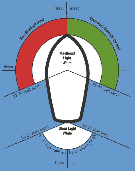
I problem I have run into in the past is what happens to navigation lights on a sailboat once you take down the masts and motor. You might still have navigation lights (the red-greens that take up 2/3 of view pointing forward, 1/3 (red) on the left and 1/3 (green) on the right. There is also a stern light, white, which takes 1/3 of the view pointing directly back. In my case the red-greens were mounted on the front of the mast, and there was no stern light, so I was left with no navigation lights. But whatever the case the steaming light (white, 2/3 of the view pointing forward) is halfway up the mainmast, and that goes down with the mast, as does the anchor light, 360º, atop the mainmast.

There are two additional problems, which have to do with human nature. There will generally be some sailboats around when you go sailing, but when you take your sailboat motoring, along rivers and canals, you are likely to encounter many more motorboats than sailboats, and naturally the motorboat drivers won't be looking out for sailboats—they will be looking out for other motorboats. Anybody who can drive a boat can read the red-green-white navigation lights, but the steaming light halfway up the mast is not obvious, because motorboats generally have a steaming light directly on top of the pilot house. Nor are they likely to spot your anchor light, hanging up in the heavens 50 feet up where they are definitely not looking, hidden among the fixed planets of the celestial sphere, and if you have no other lights on will narrowly avoid plowing directly into you in the dark. I have learned this the hard way, and now only use the anchor light if I am anchored next to a bunch of sailboats (that have their anchor lights on—a rarety) but I leave the nav lights on all night otherwise. This doesn't seem to raise any questions with anyone, but causes everyone to slow down and proceed with caution because a stationary vessel with nav lights on is an unusual sight.

And so I see absolutely no reason not to fit QUIDNON with the following lights:

• Red-green nav lights on each side of the bow, right below the rail, as shown

• White stern light on the aft edge of the aft arch

• Steaming light on the forward edge of the forward arch

• No anchor light. To achieve the same effect, turn both the steaming and the stern light on at the same time. Their illuminated sectors together add up to 360º.

Other combinations just don't work. Putting lights on masts doesn't work with the masts down. Puttling lights on top of the arches will get them smashed by the boom sweeping across in no time. Putting a steaming light on the front of the foremast will make it snag the sail parrels on the way up and down the mast.

I'll try to come up with updated drawings as time allows.


Wednesday, February 4, 2015

The final sketch


A lot of little details got tweaked in the process of presenting the various aspects of this design and taking in all the suggestions that came back. The draft (with the appendages up) got even shallower; it is now down to just two feet. The construction technique changed from the original plan, from very a adventurous combination of concrete/plywood/fiberglass to very conventional, proven glue&screw fiberglass-clad plywood core. The bottom acquired copper cladding. Headroom in the pilot house got boosted to six feet (it is, after all, a houseboat, so anything less than six feet of headroom throughout would be simply unacceptable). It acquired gunwales with scuppers, deck beams, and a large raised hatch/skylight in the middle of the deck with boom gallows right above for hoisting cargo in and out of the cabin.

The next phase is to enter the sketches into CAD, and after that will come a scale model, epoxied together out of thin plywood forms milled out on an NC machine, to do stability and towing tests, and to figure out the exact weight and placement of ballast. I might even splurge on an RC set and, since I'll be back in Boston, try sailing it around the dedicated model sailboat testing pool on the Esplanade. My goal is to draw up a full set of drawings together with a set of NC mill paths for the plywood pieces.

After any final comments, this blog is going to sleep until further notice. Since I will announce any new developments right here, please sign up to receive them. It's been fun, and very useful. Thank you all for your comments.

Friday, January 30, 2015

Construction plan

This will be the last post in this series. The design of QUIDNON is far enough along to start entering actual engineering drawings into CAD. The plan is to use an NC mill to cut out quite a lot of the plywood shapes. To be sure, there will still be some pieces that will end up being precision-fitted using a Sawzall and a grinder.

The main assembly technique is what's known as “glue and screw”: some piece of the hull is covered with a thin layer of epoxy, and the next piece is laid over it and screwed down using square-drive stainless steel screws. Each piece to be screwed on is pre-drilled with countersink holes, so that the screws pull the pieces together very tight, squeezing out excess epoxy and creating a very tight bond.

Once the plywood shapes are cut out, construction will proceed roughly as follows.

1. On a large flat surface (preferably a hangar of some sort, with a concrete floor), the outer layer of panels that will make up the perfectly flat deck will be laid out, inner side up. The deck will be made of 18 4x8 panels of 3/8 plywood. Nylon straps will be laid underneath the plywood, to make it possible to pull the hull together, and to lift it by crane when the time comes.

2. The inner layer of panels that make up the deck is then glued&screwed to it. These panels are laid out so that the joints are all staggered nicely. The inner layer's edge is in 1.5" from the outer layer, creating a ledge. The ledge is scraped clean of epoxy after it sets but before it hardens.

3. The first deadlight strip is glued&screwed to the underside of the deck, all around, using the ledge as a guide. The screws are directed at a 45° angle down. Two more layers of deadlight strips are laid down, building up the thickness to 1.2". These are precision machined so that the deadlight holes match up. The outermost strip is 1" narrower than the other two, creating a ledge, which is scraped clean of epoxy.

4. The innermost layers of the topsides, the bottom and the transom are glued&screwed together, using 6"-wide strips of epoxy to cover the seams on the inside, and laid aside.

5. The bulkheads are assembled and framed using fir 2x4's, which are cut to the right bevel using a table saw, and glued&screwed to the underside of the deck.

6. The pre-assembled topsides and transom are maneuvered into position and glued&screwed to the deadlight strips, using the ledge as a guide, but the screws are not yet tightened.

7. The pre-assembled bottom is overlaid over the bulkheads, maneuvered into position, and screwed down at the bow.

8. The sides and the bottom are pulled together using straps and bits of angle iron to align the chines. Open stretches of the joint between the topsides and the bottom are saturated with epoxy. The screws joining the topsides to the deadlight strip are tightened, and the epoxy is allowed to set.

9. Once the epoxy has set, the straps are removed and the places on the chines which they masked are saturated with epoxy. The inside corner of the chines is filleted with thickened epoxy.

10. The hull is built up by glue&screwing additional layers of plywood to the topsides, the transom and the bottom. After each layer is added, the chines are fiberglassed with a layer of fiberglass tape.

11. Once the hull is built up to full thickness (3 layers of 1/2" plywood all around, 4 at the bottom). The chine runners are built up. The outermost layer of the bottom contains chine runners, to which additional crescents of plywood are epoxied and glassed to build up the chine runners to a 2" thickness.

12. Fiberglass mat is nailed to the topsides using bronze annular nails, saturated with epoxy, and ground off along the deadlight strips and the chines.

13. Three layers of fiberglass cloth are draped over the entire structure, deadlight strips included, and saturated with epoxy.

14. The bottom is barrier-coated, then bronze sheets are laid on the bottom and screwed down, each screw bedded with 3M 5200.

15. The topsides and the deadlight strips are faired and sanded for a flat surface, then primed and painted. The topsides are painted black for the best passive solar performance. The deadlight strips are left with the bright white primer, because they will be overlaid with bronze lexan which will give them color.

16. The hull is flipped over. The deck is covered with fiberglass mat (nailed down with bronze annular nails) and saturated with epoxy.

17. Three layers of fiberglass cloth are draped over the deck and saturated.

18. Aluminum diamond plate is overlaid on the deck and screwed down with screws bedded with 3M 5200.

19. Deck beams and gunwales (which are steamed out of solid hardwood) are lag-bolted up through the deck and to each other, sealed with epoxy, primed and painted.

20. The hull is now complete, ready to receive the pilot house and the cabin can be outfitted.

Thursday, January 29, 2015

Electrical system

The primary purpose of QUIDNON is to serve as a floating residence. As such, it has to provide all the usual services that normally involve electricity: refrigeration, lighting, communications and the ability to charge mobile devices (cell phone, tablets, laptops). Where the energy for all this comes from depends on where the boat is. While marinas provide shore power (in North America this is either 30A or 50A 110VAC), this power is unavailable when living at anchor or at a mooring (the two most economical ways to live, since in many places, in Northeastern US especially, marina slip fees can add up to almost as much as renting an apartment on land.

With this in mind, I plan to equip QUIDNON for both marina living and for anchoring out. The elements I intend to use to piece together this system are all proven ones—I have used them all and found that they work and hold up extremely well. They are also all relatively cheap, by virtue of the fact that the word "marine" does not occur in their product descriptions.

When living at the marina, the usual procedure is to plug in a shore power cable and leave the battery charger on all the time. This keeps the batteries topped off all the time and in the fully charged state they last a very long time. Should shore power ever fail (because of a black-out or a transformer blow-out) the batteries provide uninterrupted power. When setting up a boat for marina living, it is very important to replace the stock shore cable plug with a SmartPlug, because the stock plug tends to burst into flames and burn the boat down. This almost happened to me—twice!

When living at a mooring or at anchor, QUIDNON has to generate its own electricity. During the summer months solar panels provide plenty of juice, but during the winter, when there is little sun, and when the solar panels are often covered up by snow, having a wind generator is very helpful. The usual procedure on yachts is to mount the wind generator atop a 10-foot pole, but that really doesn't get it up where the wind is strong, limiting its usefulness. On QUIDNON, there is not even a place to put a 10-foot pole that wouldn't interfere with the sails or the sheets, and so the only place to put wind generators is atop the masts, where there is room for two of them. This configuration is not recommended while sailing out on the ocean: the amount of windage and weight up top would pose a danger. But since the masts are easy to take down and put up, it's quite possible to have two configurations available, one for shoreside living, with two wind generators up top, and another for cruising, with the mastheads taken up with VHF antennae, nav/anchor lights and a wind instrument.


My favorite choice for a wind generator is a Sunforce 44444 which puts out a maximum of 400W (though it hardly ever blows that hard). Previous versions haunted the harbor with an interesting wailing/keening/whispering noise, which scared off seagulls, cormorants and neighbors alike, but the carbon fiber blade design has since been improved, and the latest version is quiet enough to use in a marina.


For solar panels, my current favorite choice is Renegy's 100W polycrystalline panels.


They are manufactured with a strong aluminum frame, and bolt down nicely to aluminum square channel using the supplied brackets, making installation easy. QUIDNON's pilot house roof can accommodate 8 of these, with room to spare:

Then there is the question of where to store all this power. My solution, which I know works well from experience, is to use Trojan T-105 6V 125Ah batteries. I plan to put 8 of them, in 2 banks, in a large, plastic-lined, vented battery box down in the bilge, under the cabin sole.


The two requirements for the battery enclosure are that it must never leak acid into the bilge, and that any hydrogen gas generated while charging is vented overboard (hydrogen is explosive under a wide range of concentrations and its flames are hot and invisible).

With all the sundry pieces added in (charger, charge controller, inverter, shore cable and plug, circuit breakers, wiring and outlets) the budget for the entire electrical system comes in just under $6,000 or 12% of the total budget, which is quite reasonable for a comfortable off/on-grid set-up.

There is one caveat that needs to be made with regard to all electrical/electronic systems, which is that they all work until they don't, and when they stop working there is nothing to be done but replace the component that failed. In this they are quite unlike most other parts of the boat, which can be repaired, finessed, jury-rigged, stitched up, plugged up and so on. All can be said about the reliability of an electrical system is that it works at the moment, but this is no guarantee that it will still be working the next moment, no matter how "reliable" it's supposed to be or how much you paid for it. Thus, there is no way to design anything electrical to last for the life of the boat, and there is nothing to be done about it.