Over the past month I have spent some 150 hours sailing—moving south for the winter. This has given me plenty of time to rethink some elements of the QUIDNON design, and to introduce a few improvements. While some are purely products of reflection, others resulted from direct experience with a sailboat design which I found to be inadequate. Here, I will explain the changes in prose. I will come up with updated drawings as time allows.
Wheel vs. Tiller
The sailboat I have been sailing has a very traditional layout: a pedestal at the back of the cockpit, with a wheel, a throttle and a shift lever. On top of the post is a binnacle with a compass. On top of that is an instrument cluster: a GPS chartplotter, a radar and a VHF radio. It seems simple, rational, well designed. But it is also horribly constraining.
The wheel is comfortable to operate from just one position: standing directly behind it. This gets tiresome rather quickly. Other positions—sitting behind the wheel, sitting to the left or to the right, standing in front of it—don't work nearly as well. Some group of minor muscles quickly runs out of its glycogen supply, and you have to try something else—like standing directly behind the wheel again.
Now consider the tiller.
• My favorite position when conditions are calm is to lounge with my back against the back of the cockpit and the tiller protruding from my armpit, with my right or left arm draped over it.
• To steer, I just wave that arm to and fro, not even having to lift it. When the conditions are not calm at all, my favorite position is to tie a neoprene strap to the tiller, and work it with both of my feet to push it away from me.
• When I am pulling up to a dock, I like to stand on one of the cockpit seats—the one closest to the dock—look over the side and steer with my extended foot on the tiller.
• When going upwind, I like to connect an extension to the tiller, sit on the cockpit coamings (on the leeward side, since crew weight distribution doesn't matter on a big boat with a small crew, and the leeward side is more sheltered and more comfortable) and steer using the tiller extension.
• When the autopilot fails (as it does sooner or later), I can run a line from a sheet through a block to the tiller, connect a strap pulling the other way, and then adjust the lengths of the line and the strap until the boat steers itself. This is called “sheet-to-tiller steering,” and Slocum used it during his first ever solo circumnavigation. It doesn't work with wheels.
• One good, inexpensive option for an autopilot is the so-called “tillerpilot.” These are telescoping sticks that run on 12V and incorporate a fluxgate compass, a network interface (NMEA2000) that allows them to work with wind sensors, and clip to a spot on the boat and a spot on the tiller. They don't work with wheels. With wheels, the two options are a “wheel autopilot,” which uses a stepping motor and a belt and works only in calm conditions, and a “below-deck” unit that includes a compressor, a hydraulic ram and a bunch of electronics, and costs a fortune.
• Wheel steering systems have a tendency to break. There is a lot to break. There is typically a key that keeps the wheel from just spinning around on the shaft; if that little piece of metal somehow gets lost, so is your ability to steer. Then there is a chain going down the pedestal, some pulleys, and a cable that goes around the quadrant that actually turns the rudder. Tillers directly connect to the rudder shaft, typically via a hinge.
• There is often the need to fix the rudder in a certain position. With wheels, there is typically a friction knob on the side, which is tightened and loosened. It takes time to operate and never works 100%. The best solution with a tiller is a rack: the tiller clicks down onto a toothed rack; after that it doesn't move at all. This takes no time at all to operate—just push the tiller down onto the rack to fix the rudder, and pull it up again to steer.
The one advantage of wheel over tiller is that wheels can be made to apply a lot more force to the rudder. To apply an equivalent amount of force, a tiller would have to be too long to fit in the cockpit, have too wide a swing range, or require superhuman strength to operate. But a rudder that requires a lot of force to operate is a badly designed rudder. Well-designed rudders are balanced: they have just enough bias so that they trail in the water with the boat moving without fishtailing, and in calm conditions can be deflected with a fingertip.
In heavy weather, even a balanced rudder can suddenly become heavy. This is especially the case when going downwind with waves on the quarter. They tend to roll under the transom, and when they do that water washes over the rudder in the wrong direction—aft to fore—rendering it temporarily inoperative. It also has the effect of slewing the boat around. But this is where a tiller is especially useful. With a wheel, in such conditions it is necessary to quickly spin the wheel while the boat is slewing, and then control it, allowing it to spin back slowly to bring the boat back on course. This is a lot of spinning and controlling, and wears you out in no time. With a tiller, you can be comfortably seated with both of your feet on the tiller. When the big wave rolls under you, you push with your legs, and then offer some resistance to bring the boat back on course.
Cockpit layout
Having spent some 150 hours trying to get comfortable in the cockpit, I had a number of realizations.
• The cockpit can't be too wide. It must be just wide enough for the shortest crew member to be able to sit on one side with the feet on the edge of the seat on the opposite side, knees bent slightly. That, it turns out, is a key ergonomic requirement.
• The cockpit coamings must provide back support. A lot of boats have almost vertical coamings that hit you somewhere in the back with a sharp corner. The worst case scenario is that they hit you near C5 and C6 cervical vertebra. Sail a boat like that long enough, and your arms will go numb. Cockpit coamings have to be high enough so that they fully support the shoulderblades of the tallest crew member when seated upright, and the back of the head when slouched down.
• The angle of the coamings should be laid back at an angle that makes it comfortable to sit with one's back against them, legs extended forward, knees bent. Upright coamings result in something close to a fetal position, and it doesn't work for adults for any length of time.
• The tops of the coamings should provide comfortable seating as well, with the back resting against the lifelines, both along the sides and over the transom. In good conditions these are the best places to sit and enjoy the breeze and the view. These should not be obstructed with shrouds, stays, winches, cleats and other hardware. With QUIDNON there are no shrouds or stays to worry about, and there is just one massive winch—a big 3-speed crab winch that's used as both the anchor which and the halyard winch, and is mounted right in the cockpit for ease of single-handing.
Shelter
The QUIDNON design shows a big pilot house, but a far more minimalistic layout can provide reasonable comfort in most conditions and result in better sailing performance. The minimal cockpit has a floor that cuts into the space below and drains into the engine well and the anchor chain locker directly below. It has generously high coamings, sides and back, with seats on top of them, with railing that wraps around the seats to provide comfortable back support and a handhold for climbing in and out of the cockpit onto the deck. Sea cloths on the railing can be used in heavy weather. On top is either a canvas bimini or a hard fiberglass roof. In front is a fiberglass-and-lexan dodger, which shelters the companionway hatch.
Running rigging
QUIDNON's running rigging is rather simple, but it can produce a mad tangle of line in the cockpit. A good solution is to have the anchor chain/rode, the halyards and the centerboard lines come in on one side of the companionway hatch, next to the crab winch, and the sheets to come in on the other. The other lines are short and don't produce much of a mess. All of these lines should be provided with clutches. Obviously the anchor chain and rode descend directly down into the anchor locker. But so can the halyards, the centerboard control lines and the sheets, where they come to rest in canvas bags hanging from the top of the anchor locker (in which, it turns out, there is room for everything). To tidy up the cockpit, one just feeds the lines into their respective scuppers in the bottom of the cockpit, and they vanish from view!
Instruments
Putting the instruments on top of the steering pedestal, it turns out, is a spectacularly bad idea. They are expensive, fragile, and, at that location, in harm's way. In heavy weather someone might get tossed across the cockpit by a big wave, miss a handhold and rip the chartplotter or the radar directly off its mount. A much better place for the instruments is under the dodger (a hard, fiberglass and Lexan dodger) in a box that can be locked. The cockpit layout should be such that the crew member with the shortest armspan can hold the end of the tiller with one hand and operate the instruments with the other.
Remaining questions, previously left unanswered, are: 1. where to put the VHF antenna; and 2. where to put the radome.
The VHF antenna will be mounted on top of the mainmast. The logic there is that although it will only work with the mast up, when the mast is down you are either inshore or close to shore, range is not important, and a handheld VHF will do.
The radome poses a problem, because there is simply nowhere for it to live where it will not be in the way of something—the sails, or the booms, or the running rigging, and still be high up enough and yet still have an unobstructed view.
Deck beams
I previously designed QUIDNON with deck beams—transverse timbers that reinforce the mast tabernacles where they exit the deck—on top of the deck. I have since changed my mind: the deck beams are going to be below deck. Yes, they will cut into the headroom in a couple of places, but I think that this is a much better design:
• Less deck clutter: if on top, the deck beams would cause people to stumble over them in the dark, not to mention complicate the arrangement of deck chairs.
• Better structure: the hull will be formed around two very strong upside-down trapezoids, reinforced at the corners using generous triangular brackets called “knees.”
Lights
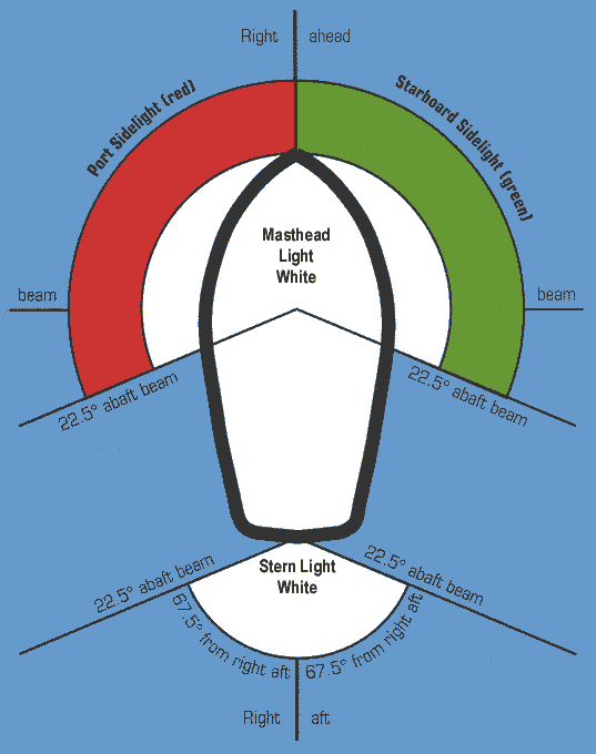
I problem I have run into in the past is what happens to navigation lights on a sailboat once you take down the masts and motor. You might still have navigation lights (the red-greens that take up 2/3 of view pointing forward, 1/3 (red) on the left and 1/3 (green) on the right. There is also a stern light, white, which takes 1/3 of the view pointing directly back. In my case the red-greens were mounted on the front of the mast, and there was no stern light, so I was left with no navigation lights. But whatever the case the steaming light (white, 2/3 of the view pointing forward) is halfway up the mainmast, and that goes down with the mast, as does the anchor light, 360º, atop the mainmast.
There are two additional problems, which have to do with human nature. There will generally be some sailboats around when you go sailing, but when you take your sailboat motoring, along rivers and canals, you are likely to encounter many more motorboats than sailboats, and naturally the motorboat drivers won't be looking out for sailboats—they will be looking out for other motorboats. Anybody who can drive a boat can read the red-green-white navigation lights, but the steaming light halfway up the mast is not obvious, because motorboats generally have a steaming light directly on top of the pilot house. Nor are they likely to spot your anchor light, hanging up in the heavens 50 feet up where they are definitely not looking, hidden among the fixed planets of the celestial sphere, and if you have no other lights on will narrowly avoid plowing directly into you in the dark. I have learned this the hard way, and now only use the anchor light if I am anchored next to a bunch of sailboats (that have their anchor lights on—a rarety) but I leave the nav lights on all night otherwise. This doesn't seem to raise any questions with anyone, but causes everyone to slow down and proceed with caution because a stationary vessel with nav lights on is an unusual sight.
And so I see absolutely no reason not to fit QUIDNON with the following lights:
• Red-green nav lights on each side of the bow, right below the rail, as shown
• White stern light on the aft edge of the aft arch
• Steaming light on the forward edge of the forward arch
• No anchor light. To achieve the same effect, turn both the steaming and the stern light on at the same time. Their illuminated sectors together add up to 360º.
Other combinations just don't work. Putting lights on masts doesn't work with the masts down. Puttling lights on top of the arches will get them smashed by the boom sweeping across in no time. Putting a steaming light on the front of the foremast will make it snag the sail parrels on the way up and down the mast.
I'll try to come up with updated drawings as time allows.
The purpose of this project is to design and mass-produce kits for a floating tiny house that can sail. It combines high-tech modeling and fabrication and low-tech assembly that can be carried out DIY-style on a riverbank or a beach. This boat is a four-bedroom with a kitchen, a bathroom/sauna, a dining room and a living room. The deck is big enough to throw dance parties. It can be used as a river boat, a canal boat or even a beach house. It's rugged and stable enough to take out on the ocean.
Thursday, September 10, 2015
Wednesday, February 4, 2015
The final sketch
A lot of little details got tweaked in the process of presenting the various aspects of this design and taking in all the suggestions that came back. The draft (with the appendages up) got even shallower; it is now down to just two feet. The construction technique changed from the original plan, from very a adventurous combination of concrete/plywood/fiberglass to very conventional, proven glue&screw fiberglass-clad plywood core. The bottom acquired copper cladding. Headroom in the pilot house got boosted to six feet (it is, after all, a houseboat, so anything less than six feet of headroom throughout would be simply unacceptable). It acquired gunwales with scuppers, deck beams, and a large raised hatch/skylight in the middle of the deck with boom gallows right above for hoisting cargo in and out of the cabin.
The next phase is to enter the sketches into CAD, and after that will come a scale model, epoxied together out of thin plywood forms milled out on an NC machine, to do stability and towing tests, and to figure out the exact weight and placement of ballast. I might even splurge on an RC set and, since I'll be back in Boston, try sailing it around the dedicated model sailboat testing pool on the Esplanade. My goal is to draw up a full set of drawings together with a set of NC mill paths for the plywood pieces.
After any final comments, this blog is going to sleep until further notice. Since I will announce any new developments right here, please sign up to receive them. It's been fun, and very useful. Thank you all for your comments.
Friday, January 30, 2015
Construction plan
This will be the last post in this series. The design of QUIDNON is far enough along to start entering actual engineering drawings into CAD. The plan is to use an NC mill to cut out quite a lot of the plywood shapes. To be sure, there will still be some pieces that will end up being precision-fitted using a Sawzall and a grinder.
The main assembly technique is what's known as “glue and screw”: some piece of the hull is covered with a thin layer of epoxy, and the next piece is laid over it and screwed down using square-drive stainless steel screws. Each piece to be screwed on is pre-drilled with countersink holes, so that the screws pull the pieces together very tight, squeezing out excess epoxy and creating a very tight bond.
Once the plywood shapes are cut out, construction will proceed roughly as follows.
1. On a large flat surface (preferably a hangar of some sort, with a concrete floor), the outer layer of panels that will make up the perfectly flat deck will be laid out, inner side up. The deck will be made of 18 4x8 panels of 3/8 plywood. Nylon straps will be laid underneath the plywood, to make it possible to pull the hull together, and to lift it by crane when the time comes.
2. The inner layer of panels that make up the deck is then glued&screwed to it. These panels are laid out so that the joints are all staggered nicely. The inner layer's edge is in 1.5" from the outer layer, creating a ledge. The ledge is scraped clean of epoxy after it sets but before it hardens.
3. The first deadlight strip is glued&screwed to the underside of the deck, all around, using the ledge as a guide. The screws are directed at a 45° angle down. Two more layers of deadlight strips are laid down, building up the thickness to 1.2". These are precision machined so that the deadlight holes match up. The outermost strip is 1" narrower than the other two, creating a ledge, which is scraped clean of epoxy.
4. The innermost layers of the topsides, the bottom and the transom are glued&screwed together, using 6"-wide strips of epoxy to cover the seams on the inside, and laid aside.
5. The bulkheads are assembled and framed using fir 2x4's, which are cut to the right bevel using a table saw, and glued&screwed to the underside of the deck.
6. The pre-assembled topsides and transom are maneuvered into position and glued&screwed to the deadlight strips, using the ledge as a guide, but the screws are not yet tightened.
7. The pre-assembled bottom is overlaid over the bulkheads, maneuvered into position, and screwed down at the bow.
8. The sides and the bottom are pulled together using straps and bits of angle iron to align the chines. Open stretches of the joint between the topsides and the bottom are saturated with epoxy. The screws joining the topsides to the deadlight strip are tightened, and the epoxy is allowed to set.
9. Once the epoxy has set, the straps are removed and the places on the chines which they masked are saturated with epoxy. The inside corner of the chines is filleted with thickened epoxy.
10. The hull is built up by glue&screwing additional layers of plywood to the topsides, the transom and the bottom. After each layer is added, the chines are fiberglassed with a layer of fiberglass tape.
11. Once the hull is built up to full thickness (3 layers of 1/2" plywood all around, 4 at the bottom). The chine runners are built up. The outermost layer of the bottom contains chine runners, to which additional crescents of plywood are epoxied and glassed to build up the chine runners to a 2" thickness.
12. Fiberglass mat is nailed to the topsides using bronze annular nails, saturated with epoxy, and ground off along the deadlight strips and the chines.
13. Three layers of fiberglass cloth are draped over the entire structure, deadlight strips included, and saturated with epoxy.
14. The bottom is barrier-coated, then bronze sheets are laid on the bottom and screwed down, each screw bedded with 3M 5200.
15. The topsides and the deadlight strips are faired and sanded for a flat surface, then primed and painted. The topsides are painted black for the best passive solar performance. The deadlight strips are left with the bright white primer, because they will be overlaid with bronze lexan which will give them color.
16. The hull is flipped over. The deck is covered with fiberglass mat (nailed down with bronze annular nails) and saturated with epoxy.
17. Three layers of fiberglass cloth are draped over the deck and saturated.
18. Aluminum diamond plate is overlaid on the deck and screwed down with screws bedded with 3M 5200.
19. Deck beams and gunwales (which are steamed out of solid hardwood) are lag-bolted up through the deck and to each other, sealed with epoxy, primed and painted.
20. The hull is now complete, ready to receive the pilot house and the cabin can be outfitted.
The main assembly technique is what's known as “glue and screw”: some piece of the hull is covered with a thin layer of epoxy, and the next piece is laid over it and screwed down using square-drive stainless steel screws. Each piece to be screwed on is pre-drilled with countersink holes, so that the screws pull the pieces together very tight, squeezing out excess epoxy and creating a very tight bond.
Once the plywood shapes are cut out, construction will proceed roughly as follows.
1. On a large flat surface (preferably a hangar of some sort, with a concrete floor), the outer layer of panels that will make up the perfectly flat deck will be laid out, inner side up. The deck will be made of 18 4x8 panels of 3/8 plywood. Nylon straps will be laid underneath the plywood, to make it possible to pull the hull together, and to lift it by crane when the time comes.
2. The inner layer of panels that make up the deck is then glued&screwed to it. These panels are laid out so that the joints are all staggered nicely. The inner layer's edge is in 1.5" from the outer layer, creating a ledge. The ledge is scraped clean of epoxy after it sets but before it hardens.
3. The first deadlight strip is glued&screwed to the underside of the deck, all around, using the ledge as a guide. The screws are directed at a 45° angle down. Two more layers of deadlight strips are laid down, building up the thickness to 1.2". These are precision machined so that the deadlight holes match up. The outermost strip is 1" narrower than the other two, creating a ledge, which is scraped clean of epoxy.
4. The innermost layers of the topsides, the bottom and the transom are glued&screwed together, using 6"-wide strips of epoxy to cover the seams on the inside, and laid aside.
5. The bulkheads are assembled and framed using fir 2x4's, which are cut to the right bevel using a table saw, and glued&screwed to the underside of the deck.
6. The pre-assembled topsides and transom are maneuvered into position and glued&screwed to the deadlight strips, using the ledge as a guide, but the screws are not yet tightened.
7. The pre-assembled bottom is overlaid over the bulkheads, maneuvered into position, and screwed down at the bow.
8. The sides and the bottom are pulled together using straps and bits of angle iron to align the chines. Open stretches of the joint between the topsides and the bottom are saturated with epoxy. The screws joining the topsides to the deadlight strip are tightened, and the epoxy is allowed to set.
9. Once the epoxy has set, the straps are removed and the places on the chines which they masked are saturated with epoxy. The inside corner of the chines is filleted with thickened epoxy.
10. The hull is built up by glue&screwing additional layers of plywood to the topsides, the transom and the bottom. After each layer is added, the chines are fiberglassed with a layer of fiberglass tape.
11. Once the hull is built up to full thickness (3 layers of 1/2" plywood all around, 4 at the bottom). The chine runners are built up. The outermost layer of the bottom contains chine runners, to which additional crescents of plywood are epoxied and glassed to build up the chine runners to a 2" thickness.
12. Fiberglass mat is nailed to the topsides using bronze annular nails, saturated with epoxy, and ground off along the deadlight strips and the chines.
13. Three layers of fiberglass cloth are draped over the entire structure, deadlight strips included, and saturated with epoxy.
14. The bottom is barrier-coated, then bronze sheets are laid on the bottom and screwed down, each screw bedded with 3M 5200.
15. The topsides and the deadlight strips are faired and sanded for a flat surface, then primed and painted. The topsides are painted black for the best passive solar performance. The deadlight strips are left with the bright white primer, because they will be overlaid with bronze lexan which will give them color.
16. The hull is flipped over. The deck is covered with fiberglass mat (nailed down with bronze annular nails) and saturated with epoxy.
17. Three layers of fiberglass cloth are draped over the deck and saturated.
18. Aluminum diamond plate is overlaid on the deck and screwed down with screws bedded with 3M 5200.
19. Deck beams and gunwales (which are steamed out of solid hardwood) are lag-bolted up through the deck and to each other, sealed with epoxy, primed and painted.
20. The hull is now complete, ready to receive the pilot house and the cabin can be outfitted.
Thursday, January 29, 2015
Electrical system
The primary purpose of QUIDNON is to serve as a floating residence. As such, it has to provide all the usual services that normally involve electricity: refrigeration, lighting, communications and the ability to charge mobile devices (cell phone, tablets, laptops). Where the energy for all this comes from depends on where the boat is. While marinas provide shore power (in North America this is either 30A or 50A 110VAC), this power is unavailable when living at anchor or at a mooring (the two most economical ways to live, since in many places, in Northeastern US especially, marina slip fees can add up to almost as much as renting an apartment on land.
With this in mind, I plan to equip QUIDNON for both marina living and for anchoring out. The elements I intend to use to piece together this system are all proven ones—I have used them all and found that they work and hold up extremely well. They are also all relatively cheap, by virtue of the fact that the word "marine" does not occur in their product descriptions.
When living at the marina, the usual procedure is to plug in a shore power cable and leave the battery charger on all the time. This keeps the batteries topped off all the time and in the fully charged state they last a very long time. Should shore power ever fail (because of a black-out or a transformer blow-out) the batteries provide uninterrupted power. When setting up a boat for marina living, it is very important to replace the stock shore cable plug with a SmartPlug, because the stock plug tends to burst into flames and burn the boat down. This almost happened to me—twice!
When living at a mooring or at anchor, QUIDNON has to generate its own electricity. During the summer months solar panels provide plenty of juice, but during the winter, when there is little sun, and when the solar panels are often covered up by snow, having a wind generator is very helpful. The usual procedure on yachts is to mount the wind generator atop a 10-foot pole, but that really doesn't get it up where the wind is strong, limiting its usefulness. On QUIDNON, there is not even a place to put a 10-foot pole that wouldn't interfere with the sails or the sheets, and so the only place to put wind generators is atop the masts, where there is room for two of them. This configuration is not recommended while sailing out on the ocean: the amount of windage and weight up top would pose a danger. But since the masts are easy to take down and put up, it's quite possible to have two configurations available, one for shoreside living, with two wind generators up top, and another for cruising, with the mastheads taken up with VHF antennae, nav/anchor lights and a wind instrument.
My favorite choice for a wind generator is a Sunforce 44444 which puts out a maximum of 400W (though it hardly ever blows that hard). Previous versions haunted the harbor with an interesting wailing/keening/whispering noise, which scared off seagulls, cormorants and neighbors alike, but the carbon fiber blade design has since been improved, and the latest version is quiet enough to use in a marina.
For solar panels, my current favorite choice is Renegy's 100W polycrystalline panels.
They are manufactured with a strong aluminum frame, and bolt down nicely to aluminum square channel using the supplied brackets, making installation easy. QUIDNON's pilot house roof can accommodate 8 of these, with room to spare:
Then there is the question of where to store all this power. My solution, which I know works well from experience, is to use Trojan T-105 6V 125Ah batteries. I plan to put 8 of them, in 2 banks, in a large, plastic-lined, vented battery box down in the bilge, under the cabin sole.
The two requirements for the battery enclosure are that it must never leak acid into the bilge, and that any hydrogen gas generated while charging is vented overboard (hydrogen is explosive under a wide range of concentrations and its flames are hot and invisible).
With all the sundry pieces added in (charger, charge controller, inverter, shore cable and plug, circuit breakers, wiring and outlets) the budget for the entire electrical system comes in just under $6,000 or 12% of the total budget, which is quite reasonable for a comfortable off/on-grid set-up.
There is one caveat that needs to be made with regard to all electrical/electronic systems, which is that they all work until they don't, and when they stop working there is nothing to be done but replace the component that failed. In this they are quite unlike most other parts of the boat, which can be repaired, finessed, jury-rigged, stitched up, plugged up and so on. All can be said about the reliability of an electrical system is that it works at the moment, but this is no guarantee that it will still be working the next moment, no matter how "reliable" it's supposed to be or how much you paid for it. Thus, there is no way to design anything electrical to last for the life of the boat, and there is nothing to be done about it.
With this in mind, I plan to equip QUIDNON for both marina living and for anchoring out. The elements I intend to use to piece together this system are all proven ones—I have used them all and found that they work and hold up extremely well. They are also all relatively cheap, by virtue of the fact that the word "marine" does not occur in their product descriptions.
When living at the marina, the usual procedure is to plug in a shore power cable and leave the battery charger on all the time. This keeps the batteries topped off all the time and in the fully charged state they last a very long time. Should shore power ever fail (because of a black-out or a transformer blow-out) the batteries provide uninterrupted power. When setting up a boat for marina living, it is very important to replace the stock shore cable plug with a SmartPlug, because the stock plug tends to burst into flames and burn the boat down. This almost happened to me—twice!
When living at a mooring or at anchor, QUIDNON has to generate its own electricity. During the summer months solar panels provide plenty of juice, but during the winter, when there is little sun, and when the solar panels are often covered up by snow, having a wind generator is very helpful. The usual procedure on yachts is to mount the wind generator atop a 10-foot pole, but that really doesn't get it up where the wind is strong, limiting its usefulness. On QUIDNON, there is not even a place to put a 10-foot pole that wouldn't interfere with the sails or the sheets, and so the only place to put wind generators is atop the masts, where there is room for two of them. This configuration is not recommended while sailing out on the ocean: the amount of windage and weight up top would pose a danger. But since the masts are easy to take down and put up, it's quite possible to have two configurations available, one for shoreside living, with two wind generators up top, and another for cruising, with the mastheads taken up with VHF antennae, nav/anchor lights and a wind instrument.
My favorite choice for a wind generator is a Sunforce 44444 which puts out a maximum of 400W (though it hardly ever blows that hard). Previous versions haunted the harbor with an interesting wailing/keening/whispering noise, which scared off seagulls, cormorants and neighbors alike, but the carbon fiber blade design has since been improved, and the latest version is quiet enough to use in a marina.
For solar panels, my current favorite choice is Renegy's 100W polycrystalline panels.
They are manufactured with a strong aluminum frame, and bolt down nicely to aluminum square channel using the supplied brackets, making installation easy. QUIDNON's pilot house roof can accommodate 8 of these, with room to spare:
Then there is the question of where to store all this power. My solution, which I know works well from experience, is to use Trojan T-105 6V 125Ah batteries. I plan to put 8 of them, in 2 banks, in a large, plastic-lined, vented battery box down in the bilge, under the cabin sole.
The two requirements for the battery enclosure are that it must never leak acid into the bilge, and that any hydrogen gas generated while charging is vented overboard (hydrogen is explosive under a wide range of concentrations and its flames are hot and invisible).
With all the sundry pieces added in (charger, charge controller, inverter, shore cable and plug, circuit breakers, wiring and outlets) the budget for the entire electrical system comes in just under $6,000 or 12% of the total budget, which is quite reasonable for a comfortable off/on-grid set-up.
There is one caveat that needs to be made with regard to all electrical/electronic systems, which is that they all work until they don't, and when they stop working there is nothing to be done but replace the component that failed. In this they are quite unlike most other parts of the boat, which can be repaired, finessed, jury-rigged, stitched up, plugged up and so on. All can be said about the reliability of an electrical system is that it works at the moment, but this is no guarantee that it will still be working the next moment, no matter how "reliable" it's supposed to be or how much you paid for it. Thus, there is no way to design anything electrical to last for the life of the boat, and there is nothing to be done about it.
Wednesday, January 28, 2015
Rudder Linkage Rethink
Jon from Virginia asked a really good question: What happens if one of the rudders gets hit sideways by something or other? Which part of the linkage gives way?
Well, this is something that does happen. I once had a towing rode get looped around the rudder blade, and it snapped my autopilot in half. After a bit of head-scratching, I came up with the following arrangement:
The stick pointing toward you is one of the tillers, which will actually be made of 1.5" round stock, but I am showing it as 1" square stock so that the drawing is easier to make and understand. The tiller is interrupted by 3 hinged plates (the axes of the hinge pins are shown in red). Front and back plates are welded to the tiller, and the front part of the tiller flops back and forth freely on the hinges. To stop that from happening under normal conditions, the two sides of the tiller are held together using a spring (here shown as a pink rubber band, to make it easier to draw, and also to be funny).
Under normal conditions, the spring is tight enough so that the hinges do not open. But under extreme overload conditions, the spring stretches, and one of the two hinges opens up, allowing the tiller to bend. When the extreme overload is removed, the spring snaps the plates back together, and all is well again.
In the real set-up, the spring will be tensioned using a bolt, to make the action adjustable. I will probably make it extra-tight to start with, then make it looser as I sail until it becomes a bit too loose, then tighten it up some, and leave it that way.
Nice feature of this set-up are:
• that the rudder linkage will not only refuse to destroy itself when a rudder blade is hit from the side, but
• that it will still be trying to steer, as well as possible under the circumstances,
• that one rudder going out commission temporarily will not affect the ability to steer with the other rudder, and
• that it will snap back into shape spontaneously and go right back to work once the overload condition is past.
Lastly, there is the need to do "back-end alignment" to make sure that the two rudder blades are perfectly symmetrical and don't cause any extra drag. To do this, I intend to add a bolt and a jam nut that goes through the outer one of the three plates on one of the tillers and pushes against a divet drilled into the next plate, opening the hinge up a crack.
I feel much better about it now.
Well, this is something that does happen. I once had a towing rode get looped around the rudder blade, and it snapped my autopilot in half. After a bit of head-scratching, I came up with the following arrangement:
The stick pointing toward you is one of the tillers, which will actually be made of 1.5" round stock, but I am showing it as 1" square stock so that the drawing is easier to make and understand. The tiller is interrupted by 3 hinged plates (the axes of the hinge pins are shown in red). Front and back plates are welded to the tiller, and the front part of the tiller flops back and forth freely on the hinges. To stop that from happening under normal conditions, the two sides of the tiller are held together using a spring (here shown as a pink rubber band, to make it easier to draw, and also to be funny).
Under normal conditions, the spring is tight enough so that the hinges do not open. But under extreme overload conditions, the spring stretches, and one of the two hinges opens up, allowing the tiller to bend. When the extreme overload is removed, the spring snaps the plates back together, and all is well again.
In the real set-up, the spring will be tensioned using a bolt, to make the action adjustable. I will probably make it extra-tight to start with, then make it looser as I sail until it becomes a bit too loose, then tighten it up some, and leave it that way.
Nice feature of this set-up are:
• that the rudder linkage will not only refuse to destroy itself when a rudder blade is hit from the side, but
• that it will still be trying to steer, as well as possible under the circumstances,
• that one rudder going out commission temporarily will not affect the ability to steer with the other rudder, and
• that it will snap back into shape spontaneously and go right back to work once the overload condition is past.
Lastly, there is the need to do "back-end alignment" to make sure that the two rudder blades are perfectly symmetrical and don't cause any extra drag. To do this, I intend to add a bolt and a jam nut that goes through the outer one of the three plates on one of the tillers and pushes against a divet drilled into the next plate, opening the hinge up a crack.
I feel much better about it now.
Tuesday, January 27, 2015
Steering linkage
![]() |
One interesting feature of this linkage is that it makes it possible to switch between wheel steering and tillerpilot steering at the pedestal. The wheel can be disconnected from the steering linkage simply by pulling back on it, causing the pinion gear splined to its shaft to disconnect from the rack which it drives. This is useful, because it lessens the inertial load on the tillerpilot from the angular momentum of the wheel. My preferred tillerpilot (Simrad TP32) can generate up to 100 lbs of force, but with considerable power drain and wear. With the wheel disconnected, the force required from it will be low, because the linkage is of lightweight aluminum and the rudders are balanced.
Another interesting feature this linkage makes possible is the ability to slow down the boat by toeing in the two rudders. That's right, unlike just about every other boat, QUIDNON will have a brake lever! The lever at the steering pedestal will drive a cable leading aft, which will act on the steering linkage to toe in the rudders. This feature will be useful when running downwind in overly boisterous conditions, because it will slow down the boat while pulling down the transom, lessening the likelihood of broaching or pitch-poling, and making it unnecessary (in most conditions) to use any of the usual techniques for slowing the boat down, such as trailing warps or deploying a drogue or a sea anchor.
Referring to the schematic diagram below, the green vertical plane on the left is the transom. The two rudder shafts are mounted to the outside of it, using brackets. Each rudder shaft is joined to a tiller through a horizontal pivot (axes of the pivot points are shown in blue) and each tiller is joined to one end of a tie-rod using vertical pivots. At its center the tie-rod is joined to the aft whip-stalk using a two-axis pivot (left/right and fore/aft). Steering action is indicated using red and green arrows (red for starboard, green for port).
The aft whip-stalk is connected to the steering shaft through a fore-and-aft pivot. The steering shaft is mounted to the deck by brackets and rocks left/right along the centerline of the boat. It penetrates the aft wall of the pilot house and runs forward to the steering pedestal.
The forward whipstalk is connected directly to the steering shaft inside the pedestal. At the top of the forward whipstalk is a rack, which is moved left/right by a pinion gear splined to the wheel shaft. The forward whip-stalk also holds a pin (not shown) for mounting a tillerpilot. Before engaging the tillerpilot, the tip of its telescoping arm is snapped onto the pin, and the wheel is pulled back on its shaft, disengaging the pinion from the rack in order to reduce the load on the tillerpilot.
Magenta arrows indicate the action of the brake lever. When actuated, it introduces a bend into the aft whipstalk, making it shorter. In turn, this causes the two tillers to pivot down. Because of the angle of the rudder posts, this has the effect of towing in the rudder blades by a few degrees.
Referring to the diagram above, the axes of the tillers incorporate a 10º twist, each in the opposite direction. Because of this deviation from horizontal, when the tie-rod (shown here in cyan) is pulled down, the rudder posts (yellow) rotate inward. When the rudder blades are towed in, they pull down the transom and induce drag. Note that it will still be possible to steer the boat even with the rudders toed in.
Monday, January 26, 2015
Concrete Bottom Rethought
I haven't studied concrete to any great extent—up until now. It is ubiquitous, and is one of the most ancient and well-understood construction materials, right after mud brick and plaster. It has a bad reputation as a boatbuilding material because of all the failed ferrocement projects, but that's not concrete, that's cement plaster over wire mesh. I was planning to do something different: create a steel-reinforced concrete slab for the bottom. And so I delved into the details on engineering concrete slabs, and came up with an answer that didn't please me at all.
Concrete has excellent compressive strength, and unreinforced concrete blocks can be stacked miles high before the bottom-most blocks gets crushed. But its strength under tension is more or less nonexistent, and to avoid placing it under tension ancient builders had a rule that the compressive force has to be concentrated within the middle third of a column. Modern builders work around this problem by making concrete into a composite, by embedding a rebar cage or mesh in a concrete slab, with enough thickness on either side so that when, under load, the armature stretches, the slab bends hardly at all. Because, it did bend, cracks would instantly open up on the convex side, letting in moisture, causing the rebar to corrode, expand, and cause “spalling” (meaning the concrete structure falls apart). What's more, this is bound to happen eventually in any case, and so reinfoced concrete slabs are engieered for eventual failure by being over-reinforced and under-cemented, because then they give warning of impending disaster in the form of cracks, as opposed to failing catastrophically.
Neither “eventual failure” nor “failing catastrophically” sounded good to me, and so I set out to calculate the required concrete slab thickness for QUIDNON's bottom, and came up with 6 inches. That translates to 16 tons of weight, not counting the rebar, the sides, and all the other structures I wanted to cast into the bottom. With all of that, the weight would push 20 tons of ballast, and that's just too much.
Also keep in mind that nobody has ever tried to join a concrete bottom to a plywood top, so I would be doing something rather experimental, if not to say adventurous. And adventurousness is, to me, akin to incompetence: I like my engineering tasks to be as boring as possible. The fun part comes after I do my boring engineering work, build it, and hand it over to other people to try to destroy. And find that they can't without trying really really hard. In general, there are two approaches to solving engineering problem: look it up (best) and guess the answer (not as good). In this case, I would only know that I guessed right if I manage to sail QUIDNON in all sorts of conditions and observe that nothing catastrophic happens, so I'd rather adhere to the much safer “look it up” strategy.
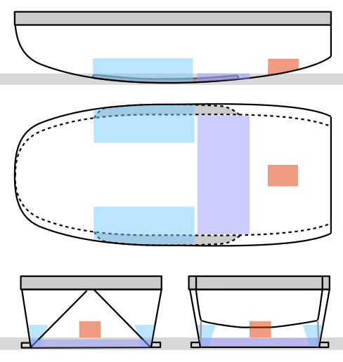
And so I decided to backtrack, and make the bottom out of plywood and fiberglass. The boat still needs ballast. There will be 5.8 tons of water ballast, which is good, but most of it is forward of the center-line. It needs to be balanced by about as much ballast aft. It works out to a 1-foot-thick slab of reinforced concrete located aft of the centerboard trunks, between the trunks and the aft cabins, under the galley, the heads and the companionway ladder. It will incorporate a rebar cage, located about 2 inches up from the bottom of the slab. That's because this concrete slab will serve as the mast step for the mainmast, taking a compression load from it, which will stretch the rebar at the bottom while compressing the concrete at the top. Here it is, shown in purple:
In addition to providing a counterbalance to the water ballast and serving as a mast step, the concrete slab will provide thermal mass. I will pour it over a few layers of dry fiberglass cloth encapsulated in plastic, to thermally insulated it from the hull and from the seawater below, and I will provide a couple of air conduits through it. One of them will be used for the exhaust of a rocket stove, to heat it up; the other will be used as part of the interior ventilation system, to keep the cabin warm. I will cover the rocket stove design in a future post.
As for the foremast step, that will just be a fat stick of wood spanning the width of the hull. I'll fiberglass the bottom of the stick, to take the tension load, so that the load on the stick itself is purely compressive.
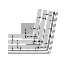
As far as joining the bottom to the sides, I intend to follow the procedure that Chris Morejohn used on HOGFISH and his other designs: screw, glue and tape. I don't have his drawings with me, but from memory it looks something like this:
The edges of the plywood are screwed together, the joint is saturated with thickened epoxy with a high-strength adhesive filler, then fiberglass tape is applied over the joint, and then the procedure is repeated, screwing and gluing each additional layer of plywood until the right thickness is reached. Then the whole structure gets covered with fiberglass mat, which is nailed down using bronze annular nails, and saturated with epoxy. Then three layers of fiberglass cloth are applied over that. Then the topsides are made smooth using fairing compound, primed and painted. In the case of QUIDNON, the bottom will receive a layer of copper cladding, so that it never needs painting.
"What a boring design!" you might say. But that's how I like it. The fun part will be in seeing how it performs in big waves and lots of wind.
Concrete has excellent compressive strength, and unreinforced concrete blocks can be stacked miles high before the bottom-most blocks gets crushed. But its strength under tension is more or less nonexistent, and to avoid placing it under tension ancient builders had a rule that the compressive force has to be concentrated within the middle third of a column. Modern builders work around this problem by making concrete into a composite, by embedding a rebar cage or mesh in a concrete slab, with enough thickness on either side so that when, under load, the armature stretches, the slab bends hardly at all. Because, it did bend, cracks would instantly open up on the convex side, letting in moisture, causing the rebar to corrode, expand, and cause “spalling” (meaning the concrete structure falls apart). What's more, this is bound to happen eventually in any case, and so reinfoced concrete slabs are engieered for eventual failure by being over-reinforced and under-cemented, because then they give warning of impending disaster in the form of cracks, as opposed to failing catastrophically.
Neither “eventual failure” nor “failing catastrophically” sounded good to me, and so I set out to calculate the required concrete slab thickness for QUIDNON's bottom, and came up with 6 inches. That translates to 16 tons of weight, not counting the rebar, the sides, and all the other structures I wanted to cast into the bottom. With all of that, the weight would push 20 tons of ballast, and that's just too much.
Also keep in mind that nobody has ever tried to join a concrete bottom to a plywood top, so I would be doing something rather experimental, if not to say adventurous. And adventurousness is, to me, akin to incompetence: I like my engineering tasks to be as boring as possible. The fun part comes after I do my boring engineering work, build it, and hand it over to other people to try to destroy. And find that they can't without trying really really hard. In general, there are two approaches to solving engineering problem: look it up (best) and guess the answer (not as good). In this case, I would only know that I guessed right if I manage to sail QUIDNON in all sorts of conditions and observe that nothing catastrophic happens, so I'd rather adhere to the much safer “look it up” strategy.
And so I decided to backtrack, and make the bottom out of plywood and fiberglass. The boat still needs ballast. There will be 5.8 tons of water ballast, which is good, but most of it is forward of the center-line. It needs to be balanced by about as much ballast aft. It works out to a 1-foot-thick slab of reinforced concrete located aft of the centerboard trunks, between the trunks and the aft cabins, under the galley, the heads and the companionway ladder. It will incorporate a rebar cage, located about 2 inches up from the bottom of the slab. That's because this concrete slab will serve as the mast step for the mainmast, taking a compression load from it, which will stretch the rebar at the bottom while compressing the concrete at the top. Here it is, shown in purple:
In addition to providing a counterbalance to the water ballast and serving as a mast step, the concrete slab will provide thermal mass. I will pour it over a few layers of dry fiberglass cloth encapsulated in plastic, to thermally insulated it from the hull and from the seawater below, and I will provide a couple of air conduits through it. One of them will be used for the exhaust of a rocket stove, to heat it up; the other will be used as part of the interior ventilation system, to keep the cabin warm. I will cover the rocket stove design in a future post.
As for the foremast step, that will just be a fat stick of wood spanning the width of the hull. I'll fiberglass the bottom of the stick, to take the tension load, so that the load on the stick itself is purely compressive.
As far as joining the bottom to the sides, I intend to follow the procedure that Chris Morejohn used on HOGFISH and his other designs: screw, glue and tape. I don't have his drawings with me, but from memory it looks something like this:
The edges of the plywood are screwed together, the joint is saturated with thickened epoxy with a high-strength adhesive filler, then fiberglass tape is applied over the joint, and then the procedure is repeated, screwing and gluing each additional layer of plywood until the right thickness is reached. Then the whole structure gets covered with fiberglass mat, which is nailed down using bronze annular nails, and saturated with epoxy. Then three layers of fiberglass cloth are applied over that. Then the topsides are made smooth using fairing compound, primed and painted. In the case of QUIDNON, the bottom will receive a layer of copper cladding, so that it never needs painting.
"What a boring design!" you might say. But that's how I like it. The fun part will be in seeing how it performs in big waves and lots of wind.
Subscribe to:
Posts (Atom)